Guides / Design
Machining T47 and BSA Bottom Bracket Cups: Fits and Threads
October 24, 2026
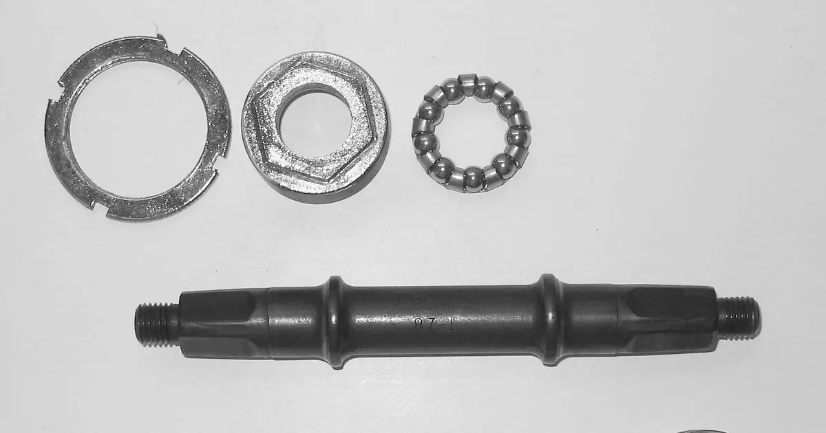
The bottom bracket is the bearing set that lets the crank spin. On a threaded frame, it is two cups that screw into the shell from each side and hold the bearings. The cups look simple, but they combine a coarse thread, a precise bearing seat, a face that must be square to both and a wrench interface. A cup that is slightly off creaks, binds or loosens, and riders blame the frame. This guide covers what a shop has to get right on BSA and T47 cups.
Standards at a glance
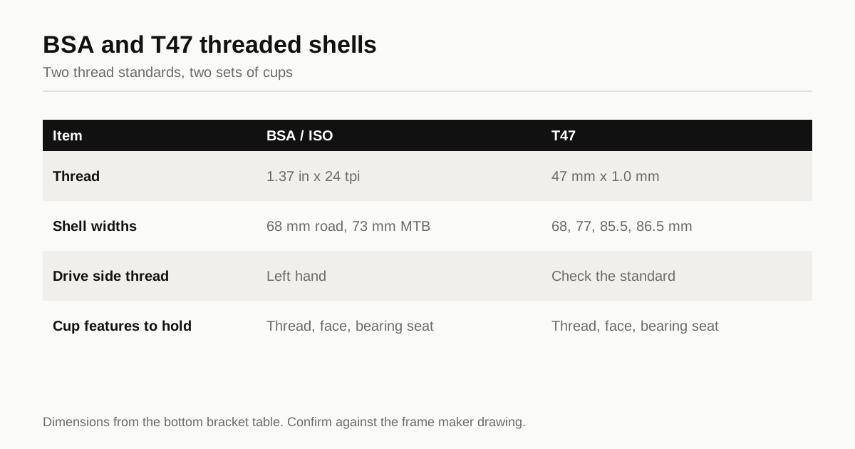
The bottom bracket table lists every common shell and thread. The two threaded standards covered here are:
| Standard | Thread | Shell widths | Notes |
|---|---|---|---|
| BSA / ISO threaded | 1.37 in x 24 tpi | 68 mm road, 73 mm MTB | Drive side cup is left-hand thread |
| T47 | 47 mm x 1.0 mm | 68, 77, 85.5, 86.5 mm | Larger thread, room for bigger bearings |
Press-fit shells such as BB30 and PF30 use a plain bore and no thread. The cups for those are a different part and rely on bore fits, as explained in the bearing fit guide.
For BSA, the left-hand thread on the drive side is deliberate. The rotation of the crank under load tends to unscrew a right-hand cup on that side, so the thread is reversed. A BSA cup made with the wrong hand cannot be installed. For T47, check the standard and the frame maker’s drawing for the thread direction on each side, and put it on your drawing.
The five features that matter
1. The thread. The thread must fit the frame shell, which was cut by someone else, often with a tap that has worn. Class tolerances matter. A thread that is too loose lets the cup wander and creak. One that is too tight binds and strips the shell, which is an expensive frame to scrap. Use thread gauges on every cup, as described in the gauging guide.
Large threads are best cut by thread milling instead of tapping, since a 1.37 inch tap takes high torque and chatters in thin walls. The thread guide explains the trade.
2. The thread form. The BSA thread follows its own cycle thread standard, so cutters and gauges must match that form and not only the diameter and pitch. Check the flank angle and profile against the standard before cutting. Confirm the thread standard with the shop at quoting time, and ask which gauge it uses. This is a place where a shop that does not know bike parts can cut a thread that almost fits.
3. The flange face. The face of the cup that meets the end of the frame shell must be flat and square to the thread axis. If the face is tilted, the cup sits crooked against the shell, loads one side of the bearing and the crank binds or creaks. Typical tolerances for face squareness are a few hundredths of a millimeter over the face diameter. A CMM or a precision plate and indicator checks it.
4. The bearing seat. The inside of the cup carries a bearing, such as a 6805 for a 24 mm spindle on many designs or a 6806 for larger ones. The seat bore must be round, to the right size and concentric with the thread. If the seat is off-center from the thread, the bearing runs off-axis and the spindle sees a bending load. Cut the thread, the face and the bearing seat in one setup, so they stay concentric by construction.
5. The tool interface. The outer end of the cup has a wrench interface, such as splines, flats or notches. It must match the tool the customer will use, and be strong enough to take installation torque. A rounded-off interface is a common warranty complaint. Check the tool fit against a real tool at first article.
Shell width and spacing
Both standards come in several widths, and the cup length and flange thickness depend on the shell. A cup for a 68 mm shell is not the same as one for a 73 mm shell. Spacers on the drive side adjust the chainline, as explained in the chainline table. The drawing must state the shell width and the spacer stack so the shop can machine the cup lengths correctly.
The total width of both cups must leave the right gap between them so the crank spindle seats with the right bearing preload. A cup that is a few tenths long can preload the bearings and make the drive feel stiff.
Materials
| Material | Use | Notes |
|---|---|---|
| 6061-T6 | Most cups | Good machinability, anodizes well |
| 7075-T6 | Premium cups | Stronger threads, see alloy guide |
| Stainless steel | Heavy-duty, wet climates | Strong threads, needs anti-seize |
| Titanium | Premium | Light, expensive, galls in aluminum shells |
| Engineered plastic | Low cost, some cups | Not for performance cups |
Aluminum cups in aluminum shells can gall and seize, especially after a wet winter. Many cups ship with grease or anti-seize, and some use a plated or coated thread. A steel or titanium cup in an aluminum shell risks galvanic corrosion at the thread. Apply grease at installation and say so in the instructions.
Anodizing and masking
A cup is usually anodized for cosmetics and corrosion. The coating grows into the thread and the bearing seat, which changes both. The standard options are:
- Mask the thread and the bearing seat during anodizing, so they stay at machined size.
- Cut oversize and let the coating bring the dimension into tolerance.
- Chase the thread and finish-bore the seat after anodizing.
For a coarse thread such as BSA, anodize on the flanks tightens the fit. For a bearing seat, it closes the bore. Check the numbers with the anodize growth calculator. A hard anodized thread is particularly sensitive, and masking is the safer route. The anodizing partner guide explains how to coordinate the machine shop and the finisher.
Typical process route
A turned part first, then milled for the wrench interface:
- Cut and face bar stock on a lathe
- Turn the outside, the flange and the seat in one setup
- Cut or mill the thread
- Mill the wrench interface
- Deburr and check threads and seat
- Blast, anodize and laser mark
- Final inspection with gauges
A good sequence keeps thread, face and seat in the same chucking. Parts like this are mostly turned, and a lathe with live tooling can finish most of it in one setup. The cost is dominated by cycle time and the inspection plan, as the cost guide explains.
Quality checks that catch problems
- Thread gauge on every part, with the correct hand for each side
- Seat bore with a bore gauge or air gauge
- Face squareness on a sample, and first article on a CMM
- Wrench interface test with a real tool
- Visual check for burrs in the thread start
- Anodize thickness on a sample
See the quality control guide for how much inspection to ask for.
What to put on the drawing
- Standard and shell width, with thread size, form and class
- Thread hand for each side
- Bearing part number and seat tolerance
- Face squareness and seat concentricity to the thread axis
- Wrench interface drawing and tolerance
- Material, finish, masking plan and laser mark
- Gauge requirements and sampling
Send your drawing through the RFQ page and we match you with up to 3 machine shops. They reply within 24 business hours.
See also: bottom bracket cups, shells and adapters and the bottom bracket standards chart.
Frequently asked questions
Which side of a BSA bottom bracket has the left-hand thread?
The drive side, the right side as you sit on the bike, has a left-hand thread. The non-drive side has a right-hand thread. A cup cut with the wrong hand cannot be installed, and mixing sides is the most common error in a first article.
How is T47 different from BSA?
T47 is a threaded shell with a larger 47 mm by 1.0 mm thread, which leaves room for a larger bearing and avoids some of the creaking problems of press-fit shells. BSA is the older 1.37 inch by 24 tpi thread. They are different shell sizes and are not interchangeable.
Should the cup be anodized?
Usually yes for cosmetics and corrosion, with the threads and the bearing seat controlled. Anodize grows into threads and bores, so state whether those areas are masked, chased afterward or cut oversize.
Need a quote for this part?
Send the drawing. We match you with up to 3 shops that machine bike parts and reply within 24 business hours.
Get matched with a bike parts shop